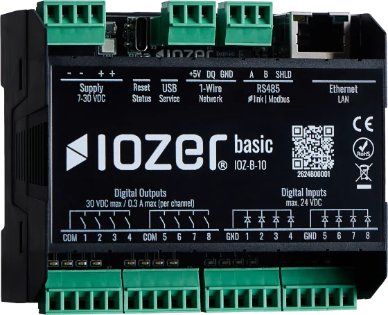
Digital outputs
The Digital outputs tab configures the local output channels.
Open I/O & Interfaces → Digital Outputs. I/O & Interfaces must be active for operation.
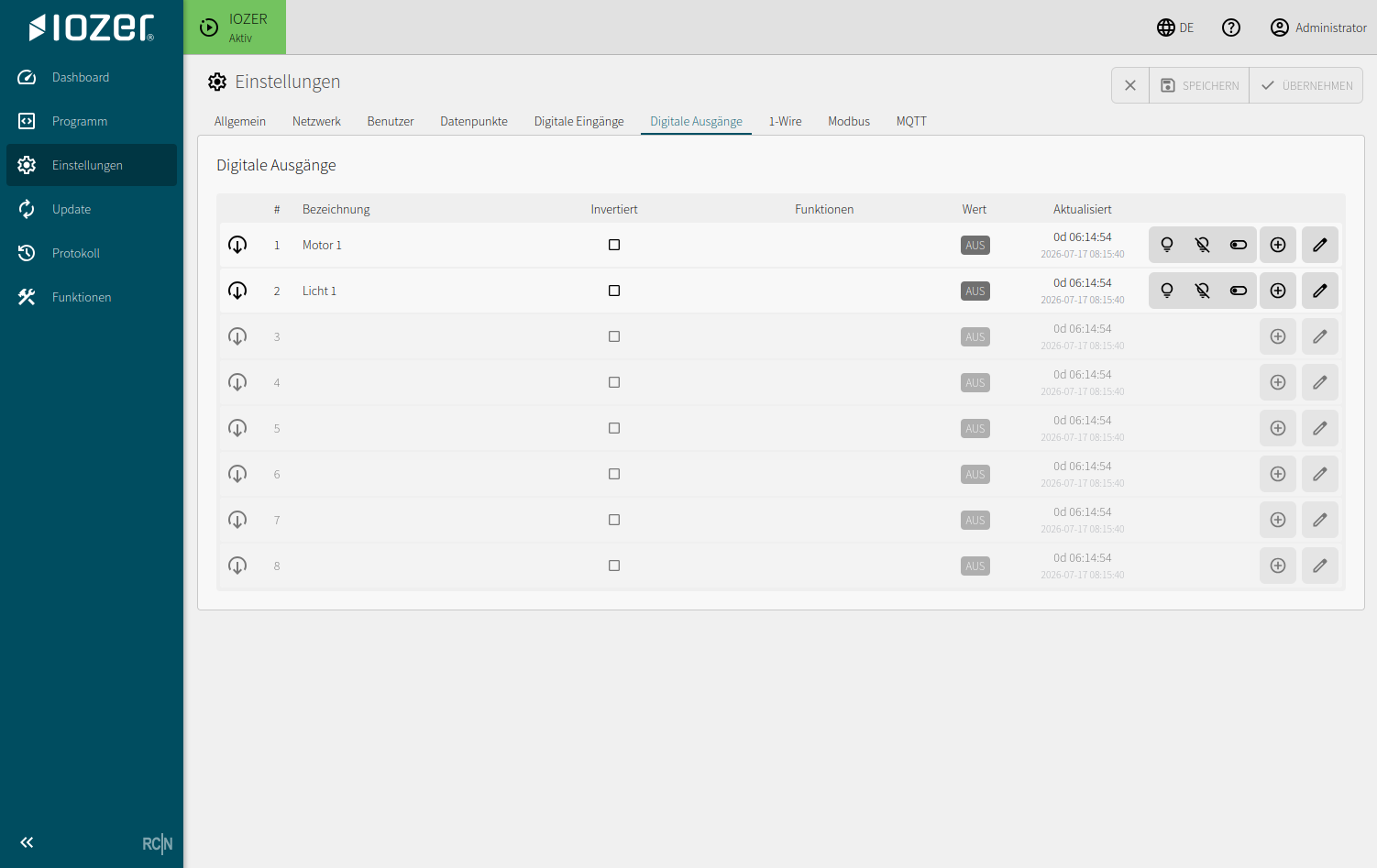
Table
| Column | Meaning |
|---|---|
| # | Physical output channel |
| Description | Human-readable description of the output |
| Inverted | Reverses the logical control of the output |
| Functions | Configured output functions |
| Value | Current logical output value |
| Updated | Age and timestamp of the most recent update |
Editing an output
Use the edit action at the end of a table row to open the detail dialog for that output.
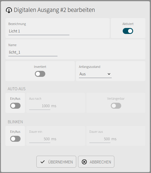
General
| Setting | Meaning |
|---|---|
| Description | Human-readable name of the output in the web interface |
| Enabled | Enables or disables control of the output channel |
| Name | Technical name used by datapoints and local logic |
| Inverted | Reverses the logical control of the output |
| Initial state | State when I/O is activated: Off, On, or restore the last saved state |
| Stop state | State when I/O is stopped: Off, On, or Keep state |
With Keep state, ongoing flashing also continues; the auto-off timeout is not evaluated while I/O is stopped. All outputs are switched off when starting in setup mode. Stopping the program alone does not stop I/O and therefore does not apply the output stop state.
Auto-off
When auto-off is enabled, the output is switched off automatically after the time configured under Off after. If Extendable is enabled, triggering the output again restarts the auto-off timer.
Flashing
When flashing is enabled, the output automatically alternates between on and off. On duration and Off duration define the two intervals.
Use
A datapoint must be created to control a digital output. Configure the output as the datapoint's data target. Program logic and interfaces set the datapoint value, which is then forwarded to the hardware channel.
Typical applications:
- Relay or switching outputs
- Enable signals
- Signaling outputs
- Local actuators
Before commissioning, verify that the inverted logic, initial state, and stop state are appropriate for the connected load and the intended safe behavior.