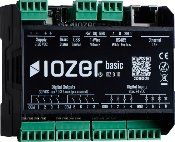
Modbus RTU to TCP Gateway
Scenario
An Eastron SDM630-Modbus V2 energy meter is connected to IOZER basic through RS485. IOZER periodically reads the measurements as a Modbus RTU master and provides them on an IP network as a Modbus TCP slave.
A Modbus TCP client can therefore access the energy meter measurements without being connected directly to the RS485 bus.

In current Modbus terminology, the roles “master” and “slave” correspond to “client” and “server.” This article uses the terms shown in the IOZER user interface.
Goal
After completing the configuration:
- IOZER basic reads twelve electrical measurements from the SDM630,
- the datapoint overview shows current and valid values,
- IOZER provides the values in holding registers over Modbus TCP, and
- a computer on the network can read the values using
mbclient.
The register addresses on the TCP side can be selected freely. This example retains the zero-based start addresses of the SDM630. The measurements move from the SDM630 input register area to the IOZER holding register area. This simplifies commissioning and subsequent mapping.
Hardware used
IOZER components
- IOZER basic (IOZ-B-10)
- Suitable 7–30 V DC SELV/PELV power supply
Additional components
- Eastron SDM630-Modbus V2
- Twisted bus cable suitable for RS485
- Ethernet or Wi-Fi network
- Computer with
mbclientfrom ModbusTools
Requirements
- IOZER basic is installed according to the safety information and connected to a suitable power supply.
- IOZER can be reached over Ethernet or Wi-Fi and has a known IP address.
- The SDM630 has been installed correctly and is connected over RS485 to the IOZER terminals
A,B, and, if required,SHLD. - The bus cable has the correct polarity. For longer cable runs, terminate the bus only at its two physical ends.
- The Modbus address of the SDM630 is known. The following steps use Unit ID
1as an example. Adjust this value if the meter uses a different address. - The following communication parameters are configured on the SDM630:
| Parameter | Value |
|---|---|
| Baud rate | 9600 bit/s |
| Data bits | 8 |
| Parity | None (N) |
| Stop bits | 1 |
Installation and work on the energy meter may only be carried out by qualified personnel while the system is de-energized.
IOZER basic must not be connected directly to mains voltage.
Implementation
1. Configure Modbus RTU
Open the IOZER web interface and navigate to I/O & Interfaces → Modbus → Modbus RTU.
Configure the RS485 interface as follows:
| Setting | Value |
|---|---|
| Mode | Master (Client) |
| Baud rate | 9600 |
| Data bits | 8 |
| Parity | None |
| Stop bits | 1 |
Then add the SDM630 as an RTU slave:
| Setting | Value |
|---|---|
| Description | SDM630_1 |
| Unit ID | 1 or the address configured on the meter |
| Timeout | Project-specific or default value |
| Retries | Project-specific or default value |
Save and apply the configuration. Activate I/O & Interfaces so that Modbus can operate; I/O is initially stopped in setup mode. No running program is required for this gateway example. Interface and status information is available under Modbus.
2. Configure Modbus TCP
Navigate to I/O & Interfaces → Modbus → Modbus TCP and configure IOZER as a Modbus TCP slave:
| Setting | Value |
|---|---|
| Mode | Slave (Server) |
| Slave port | 502 |
| Slave Unit ID | 1 |
| Max. registers | At least 24; the screenshot uses 100 |
| Multi-write | Disabled |
The TCP Unit ID can be configured independently of the RTU device address. This example uses Unit ID 1 on both sides. On the TCP side, the mapping occupies the holding registers with zero-based start addresses 0 through 23.
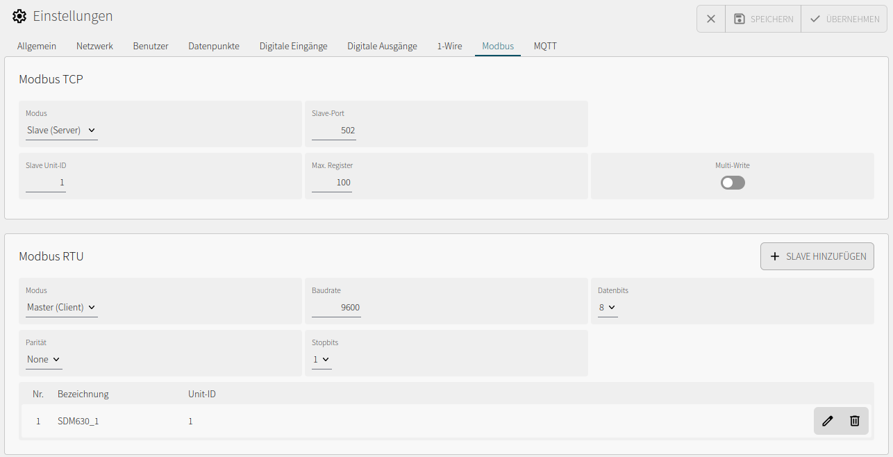
The screenshot shows the complete interface configuration used in this example. A higher value for Max. registers is permitted; the twelve Float32 values require only addresses 0 through 23.
3. Configure registers and datapoints
The SDM630 measurements shown here are located in input registers and are read using Modbus function 04. Each measurement occupies two consecutive 16-bit registers and is transmitted as a 32-bit IEEE 754 floating-point value. By default, the SDM630 provides the high-order register first. No additional scaling is required for these measurements.
Under Datapoints, create one datapoint of type Float for each measurement. IOZER address fields use the zero-based protocol address. Configure each datapoint as follows:
- Use the SDM630 on the Modbus RTU master as the data source.
- Select function
04 – Read Input Registers. - Enter the relevant zero-based RTU address.
- Select data type
Float32with the high-order register first. - Set scale to
1and offset to0. - Use the Modbus TCP slave with function
03 – Read Holding Registersas the data target. - Enter the relevant zero-based TCP address.
- Also select
Float32with the high-order register first for the TCP target.
Enable Forward to data target for each of these datapoints so that values read from the RTU device are automatically made available at the TCP data target.
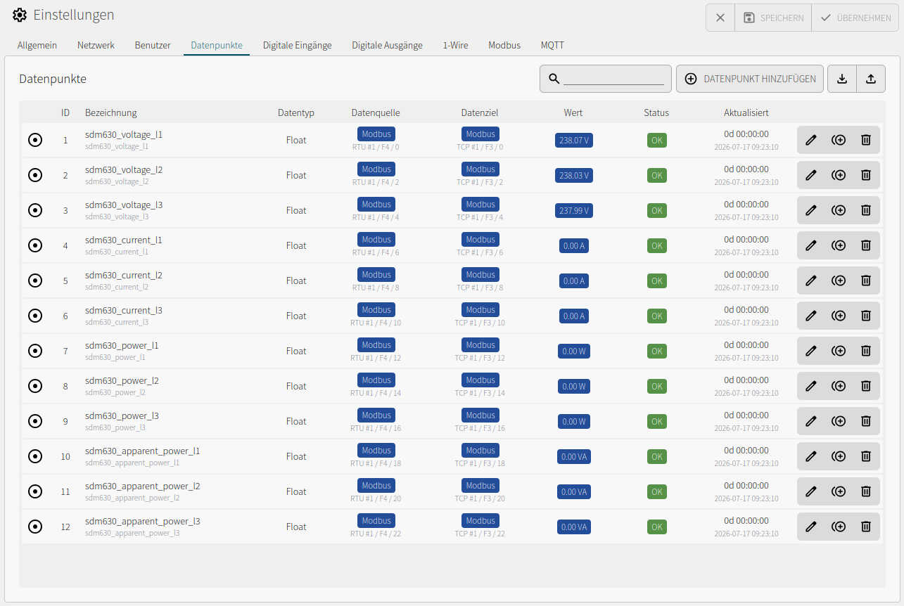
Configure the first datapoint completely and then use Copy datapoint in the datapoint overview. In each copy, change only the description, technical name, unit, and RTU and TCP addresses according to the following table. The data source, data target, data type, register order, scale, and offset can remain unchanged.
The following mapping distinguishes between the address notations used: the SDM630 column follows the five-digit notation in the official SDM630 Modbus protocol documentation, while the mbclient column uses the six-digit standard view of ModbusTools. Enter only the zero-based values in the IOZER address fields.
| Datapoint name | Measurement | Unit | SDM630 register (5 digits) | RTU address in IOZER | mbclient address (6 digits) |
TCP address in IOZER |
|---|---|---|---|---|---|---|
sdm630_voltage_l1 |
Voltage L1-N | V | 30001 |
0 |
400001 |
0 |
sdm630_voltage_l2 |
Voltage L2-N | V | 30003 |
2 |
400003 |
2 |
sdm630_voltage_l3 |
Voltage L3-N | V | 30005 |
4 |
400005 |
4 |
sdm630_current_l1 |
Current L1 | A | 30007 |
6 |
400007 |
6 |
sdm630_current_l2 |
Current L2 | A | 30009 |
8 |
400009 |
8 |
sdm630_current_l3 |
Current L3 | A | 30011 |
10 |
400011 |
10 |
sdm630_power_l1 |
Active power L1 | W | 30013 |
12 |
400013 |
12 |
sdm630_power_l2 |
Active power L2 | W | 30015 |
14 |
400015 |
14 |
sdm630_power_l3 |
Active power L3 | W | 30017 |
16 |
400017 |
16 |
sdm630_apparent_power_l1 |
Apparent power L1 | VA | 30019 |
18 |
400019 |
18 |
sdm630_apparent_power_l2 |
Apparent power L2 | VA | 30021 |
20 |
400021 |
20 |
sdm630_apparent_power_l3 |
Apparent power L3 | VA | 30023 |
22 |
400023 |
22 |
30001 is the five-digit SDM630 notation for the first input register. IOZER reads this register using function 04 and address 0. On the TCP side, IOZER provides the value using function 03, also at address 0. mbclient displays this holding register in its six-digit notation as 400001. Do not enter the digit sequences 30001 or 400001 in the IOZER address fields.
Save and apply the datapoints and check the Value, Status, and Updated columns in the overview. The values should update regularly and have status OK. The overview shows the mapping in a compact form: RTU #1 / F4 / 0 reads the first SDM630 input register; TCP #1 / F3 / 0 provides the same value in the first TCP holding register.
4. Read test using mbclient
Install and start mbclient from the serhmarch/ModbusTools project. Then create a new project.
- Add a port of type Modbus TCP.
- Enter the IOZER IP address as the host and
502as the port. - Add a device with Unit address
1to the port. - Create a data view entry for a holding register.
- Select address
400001and theFloat32orFloatrepresentation with the high-order register first. - Start communication.
ModbusTools uses six-digit register notation in its default view. The holding register at IOZER address 0 is therefore entered as 400001 in mbclient. Alternatively, select zero-based IEC 61131-3 notation under Tools → Settings → View → Modbus adr. notation; the same holding register is then shown as %MW0.
For an individual test, you can also use Tools → Send Message:
| Field | Value |
|---|---|
| Unit ID | 1 |
| Function | 03 – Read Holding Registers |
| Start address | 0 |
| Register count | 2 |
| Representation | Float32, high-order register first |
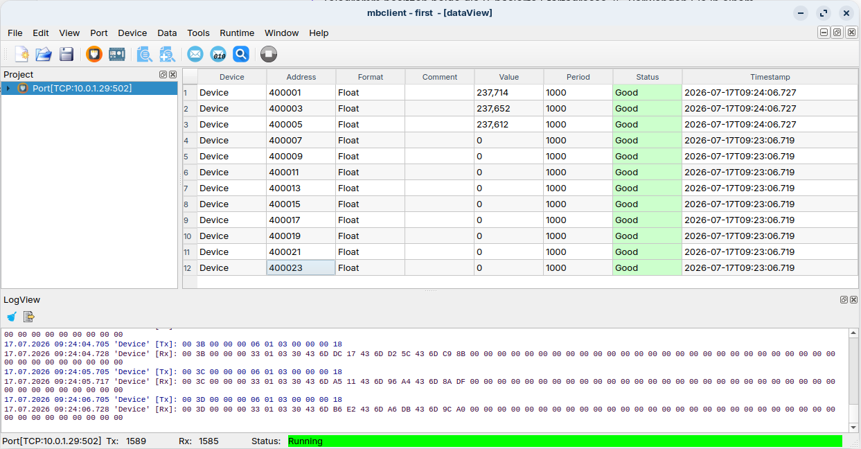
The expected result is the voltage between L1 and neutral. The value should be plausible and approximately match the SDM630 display. Additional measurements can be checked using the start addresses in the mapping table.
The screenshot shows all twelve values at mbclient addresses 400001 through 400023. Status Good confirms successful TCP communication and reading with function 03.
Troubleshooting
| Symptom | Possible cause and check |
|---|---|
| No RTU values in IOZER | Check the Unit ID, 9600 8N1, wiring of A and B, bus termination, and SDM630 power supply. |
| Modbus status reports a timeout | Check the RTU device address and cable routing, and increase the timeout if required. |
| RTU value is implausible | Check function 04, the zero-based RTU address, and Float32 with the high-order register first. |
| TCP value is implausible | Check function 03, the zero-based TCP address, and Float32 with the high-order register first. |
| Value is shifted by one register | Use the zero-based address in IOZER: 30001 in the SDM630 manual and 400001 in mbclient both correspond to IOZER address 0 within their respective register areas. |
mbclient cannot connect |
Check the IP address, TCP port 502, TCP slave mode, and network path. |
| TCP connection is established but no value is returned | Check the Unit ID, function 03, and configured TCP holding register mapping. |
Datapoint is Stale or Error |
Check the RTU slave status and the time of the most recent successful update. |
Result and extension
After a successful test, IOZER basic operates as a protocol gateway: it reads the SDM630 measurements over Modbus RTU and makes them available on the network in Modbus TCP holding registers, independently of the RS485 bus.
The same principle can be used to provide additional Modbus RTU devices over Modbus TCP. Add each device as another RTU slave and create corresponding datapoints with a Modbus TCP target for its values. Observe the following:
- Each RTU device requires a unique Unit ID.
- All devices on the same RS485 bus must use the same baud rate, parity, and number of stop bits.
- Assign each datapoint its own non-overlapping TCP register range.
- Set Max. registers high enough to fully include the highest TCP address used.
IOZER combines the values from the connected RTU devices in one shared Modbus TCP register map. A TCP client can read all provided values through the IP connection to IOZER and does not require direct access to the RS485 bus.