1-Wire to Modbus TCP
Scenario
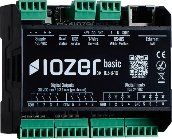
An IOZER basic reads three 1-Wire temperature sensors and writes the measurements to a Beckhoff BC9020 flag memory area over Modbus TCP. The PLC then processes the received values as temperatures in degrees Celsius.
| Component | Task |
|---|---|
| IOZER basic | Read the 1-Wire sensors and write temperatures as a Modbus TCP master (client) |
| Beckhoff BC9020 | Provide registers as a Modbus TCP slave (server) and use the temperatures in the PLC program |
On IOZER, datapoint configuration with forwarding enabled is sufficient. No Blockly or JavaScript program is required for this transfer. The Structured Text code below runs on the BC9020.
Goal
After configuration:
- IOZER reads three temperature values every five seconds,
- each temperature is transferred as a signed 16-bit value in tenths of a degree,
- the BC9020 receives the values at
%MW2,%MW4, and%MW6, and - an additional IOZER datapoint reads a life sign back from the PLC.
Hardware used
- IOZER basic (IOZ-B-10) with a suitable power supply
- Three 1-Wire sensors; two DS18B20s and one DS2438 in this example
- Beckhoff BC9020 with an operational K-bus configuration
- Shared IP network for IOZER, the BC9020, and the engineering computer
- Computer with access to the IOZER web interface and TwinCAT PLC Control
Requirements
- Devices and sensors are installed according to the safety information and electrical connection instructions.
- I/O & Interfaces are active on IOZER.
- The BC9020 is reachable; this setup uses IP address
10.0.1.19and TCP port502. - The flag addresses used below are reserved in the PLC project and are not overwritten by other logic.
- Communication intervals and the BC9020 watchdog settings are coordinated; see step 5.
Implementation
1. Configure the 1-Wire sensors
Open I/O & Interfaces → 1-Wire. Choose Start discovery, add the three sensors, and enable temperature value T for each one.
| Setting | Value |
|---|---|
| Read interval | 5 seconds |
| Temperature value factor | 1 |
| Temperature value offset | 0 |
| Unit | °C |
The example setup uses the following assignments:
| Sensor label | Type | Address in the screenshot | Datapoint created later |
|---|---|---|---|
Temperatur |
DS18B20 |
28-67-05-18-44-24-06-26 |
Temp 1 |
Temp 2 |
DS18B20 |
28-37-3C-26-45-24-06-89 |
Temp 2 |
Temp 3 |
DS2438 |
26-83-FF-19-02-00-00-FF |
Temp 3 |
Use your own sensors' addresses. For the DS2438, explicitly select temperature value T; the none (raw data) template shown in the screenshot supplies it without an additional sensor template.
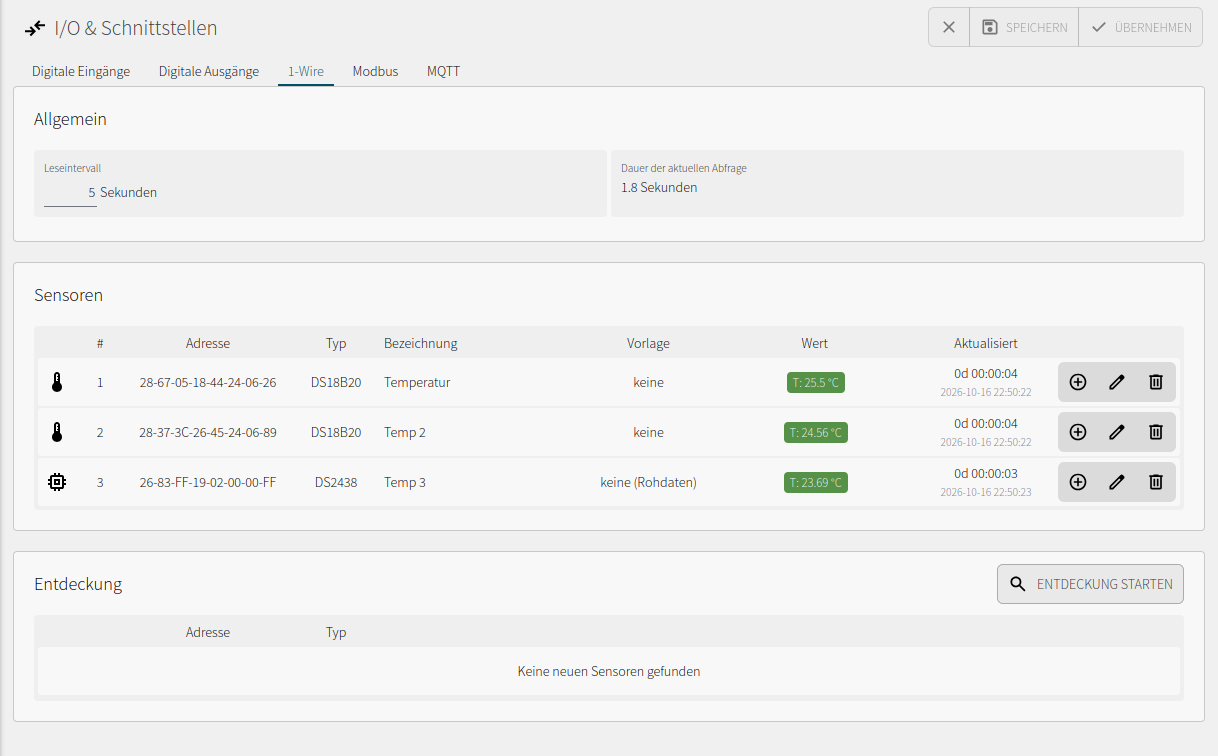
Save and apply the configuration. Check the measurements and their update times. Further details are available under 1-Wire.
2. Create the Modbus TCP connection to the PLC
Navigate to I/O & Interfaces → Modbus. Set Modbus TCP → Mode to Master (Client) and add the BC9020 using Add slave.
| Setting | Value |
|---|---|
| Label | Slave 1, as in the screenshot |
| Host | 10.0.1.19 or your BC9020's IP address |
| Port | 502 |
| Unit ID | For example, 1 |
| Timeout and retries | Suitable for the network, or default values |
| Modbus RTU | Disabled |
Slave 1 is the connection to the BC9020. IOZER operates as the client. According to the Beckhoff documentation, section 6.2.1, the BC9020 Modbus unit can be freely selected; Unit ID 1 is a choice for this example and is not displayed in the screenshot.
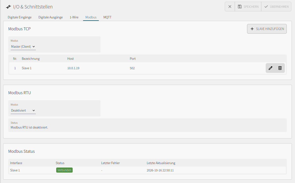
Save and apply the configuration. Under Modbus status, check that Slave 1 is Connected. A successful read or write then confirms register access.
3. Prepare registers and the TwinCAT program
The Beckhoff flag memory area for Modbus TCP starts at 0x4000, decimal 16384. This setup uses:
| Content | IOZER Modbus address, zero-based | Hexadecimal | PLC address | PLC data type | Direction |
|---|---|---|---|---|---|
| Life sign | 16384 |
0x4000 |
%MB0, second byte %MB1 reserved |
BYTE |
BC9020 → IOZER |
| Temperature 1 × 10 | 16385 |
0x4001 |
%MW2 |
INT |
IOZER → BC9020 |
| Temperature 2 × 10 | 16386 |
0x4002 |
%MW4 |
INT |
IOZER → BC9020 |
| Temperature 3 × 10 | 16387 |
0x4003 |
%MW6 |
INT |
IOZER → BC9020 |
Modbus register addresses count 16-bit words. The absolute flag addresses in this BC9020 project count bytes. Therefore, register 16385 at %MW2 is followed by register 16386 at %MW4. Enter the decimal addresses from the table directly in IOZER, without an additional 4xxxx prefix.
In TwinCAT PLC Control, create a Structured Text program named MAIN with these declarations:
PROGRAM MAIN
VAR
    lifesign AT %MB0 : BYTE;
    lifesign_high AT %MB1 : BYTE;

    temp_1_x10 AT %MW2 : INT;
    temp_2_x10 AT %MW4 : INT;
    temp_3_x10 AT %MW6 : INT;

    temp_1 : REAL;
    temp_2 : REAL;
    temp_3 : REAL;
END_VAR
Enter the following in the implementation area:
lifesign_high := 0;
lifesign := lifesign + 1;

temp_1 := INT_TO_REAL(temp_1_x10) / 10.0;
temp_2 := INT_TO_REAL(temp_2_x10) / 10.0;
temp_3 := INT_TO_REAL(temp_3_x10) / 10.0;
The life sign increments each PLC cycle. Because IOZER reads a complete 16-bit register, the additional lifesign_high variable reserves the second byte and keeps it at 0. IOZER writes the three temperature words; the PLC program converts them to REAL temperatures.
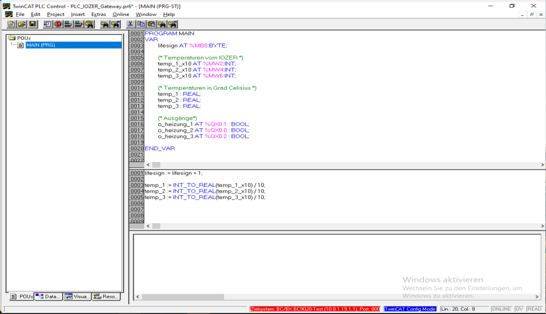
Build and download the project to the BC9020, then start the PLC. Save a boot project if required for subsequent operation.
4. Configure temperature datapoints with Modbus targets
Under Datapoints, create three enabled datapoints:
| Label | Technical name | Data type | Unit | Modbus target address |
|---|---|---|---|---|
Temp 1 |
temp_1 |
Float |
°C |
16385 |
Temp 2 |
temp_2 |
Float |
°C |
16386 |
Temp 3 |
temp_3 |
Float |
°C |
16387 |
Select classification Temperature and leave Read only off to allow forwarding to the data target.
In the Data source & target tab, first configure the source:
| Setting | Value |
|---|---|
| Binding | 1-Wire |
| 1-Wire | Temperature value T of the assigned sensor |
| Address | Hardware address of the sensor |
| Value | 0, the first measurement T in this example |
| Key | Empty |
| Forward to data target | On |
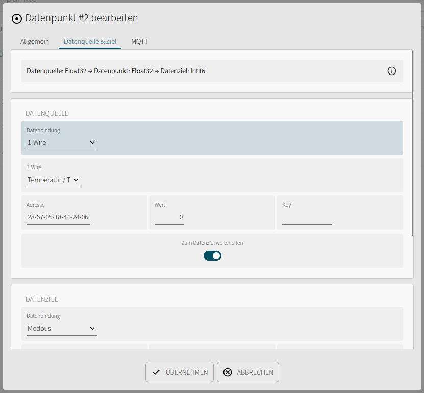
Configure the target of each temperature datapoint:
| Setting | Value |
|---|---|
| Binding | Modbus |
| Transport | TCP |
| Connection | Slave 1 |
| Function | Holding Register |
| Address | 16385, 16386, or 16387, respectively |
| Data type | Int16 |
| Write function code | Automatic |
| Scale | 0.1 |
| Offset | 0 |
| Word order | MSW first |
| Byte swap | Off |
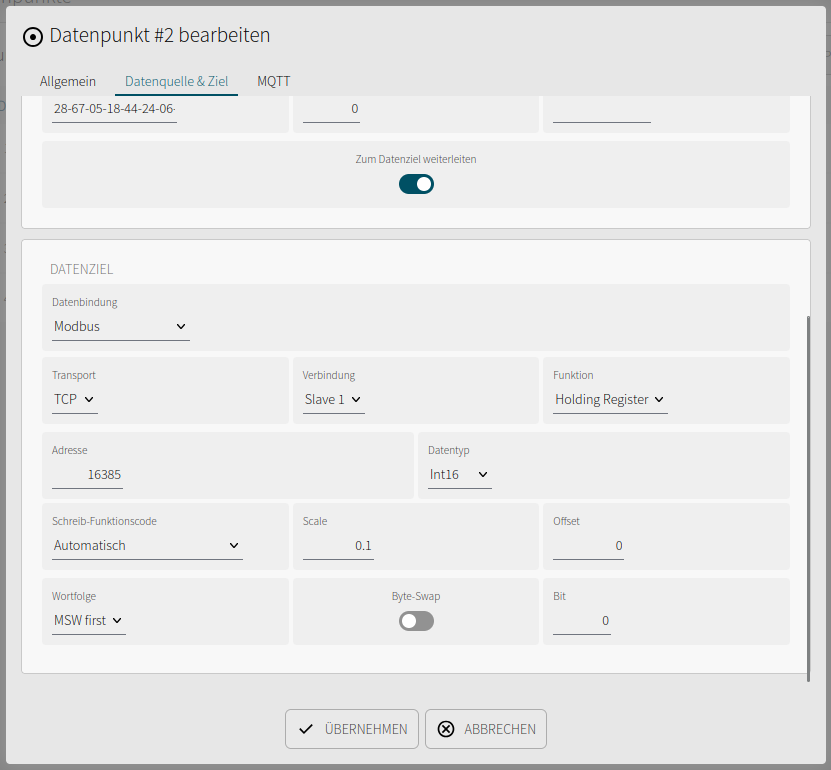
Float describes the IOZER datapoint in degrees Celsius; Int16 describes its representation at the Modbus target. IOZER uses inverse scaling when writing:
Register value = (Datapoint value − Offset) / Scale
25.5 °C / 0.1 = 255
−5.2 °C / 0.1 = −52
The register value is rounded to an integer. In the PLC, INT_TO_REAL(RegisterValue) / 10.0 converts it back to degrees Celsius with a resolution of 0.1 °C. Use Int16 in IOZER and INT in the PLC so that negative temperatures are handled correctly.
In Automatic mode, a single 16-bit holding register is written using function 06. The F3 label in the datapoint overview identifies the holding register area and is not the write command being executed.
Configure Temp 1 completely, then use Copy datapoint. In each copy, change the label, technical name, sensor source, and Modbus address according to the tables.
Save and apply the configuration. Forward to data target automatically writes the first valid source value and subsequent value changes. Unchanged measurements do not cause another write command. See Datapoint forwarding.
5. Read a life sign back from the PLC
Create an additional datapoint to read a value that changes cyclically in the BC9020:
| Setting | Value |
|---|---|
| Label | Beckhoff Lifesign |
| Name | beckhoff_lifesign |
| Datapoint data type | Integer |
| Data source → Binding | Modbus |
| Transport / connection | TCP / Slave 1 |
| Function | Holding Register, read using function 03 |
| Address | 16384 |
| Modbus source data type | UInt16 |
| Interval | 1000 ms, as in the screenshot; consider the watchdog |
| Scale / offset | 1 / 0 |
| Word order / byte swap | MSW first / Off |
| Data target | None |
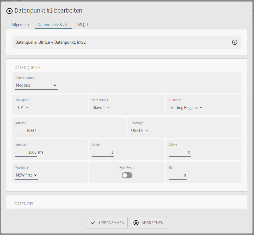
The PLC counter is declared as a BYTE and wraps after 255. The value read therefore does not have to increase continuously. The life sign checks the return path and PLC program execution; also verify temperature transfer in TwinCAT.
Beckhoff documents a watchdog enabled by default at 1000 ms. The read interval shown leaves no timing margin. Coordinate the interval and watchdog with a margin. Reads can service the watchdog in telegram mode; they are insufficient in write-telegram mode. Temperature forwarding writes only on changes. See Beckhoff Modbus TCP watchdog.
6. Verify the transfer
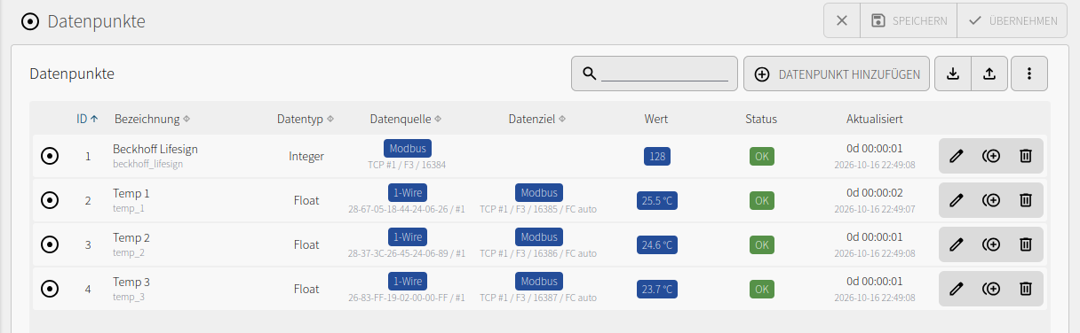
Check the IOZER datapoint overview. The three temperatures and the life sign should show valid values with status OK.
Open the online view of MAIN in TwinCAT. Check the raw values and the temperatures calculated from them. The supplied screenshot shows:
| Variable | Raw value | Calculated temperature |
|---|---|---|
temp_1_x10 → temp_1 |
252 |
25.2 °C |
temp_2_x10 → temp_2 |
246 |
24.6 °C |
temp_3_x10 → temp_3 |
239 |
23.9 °C |
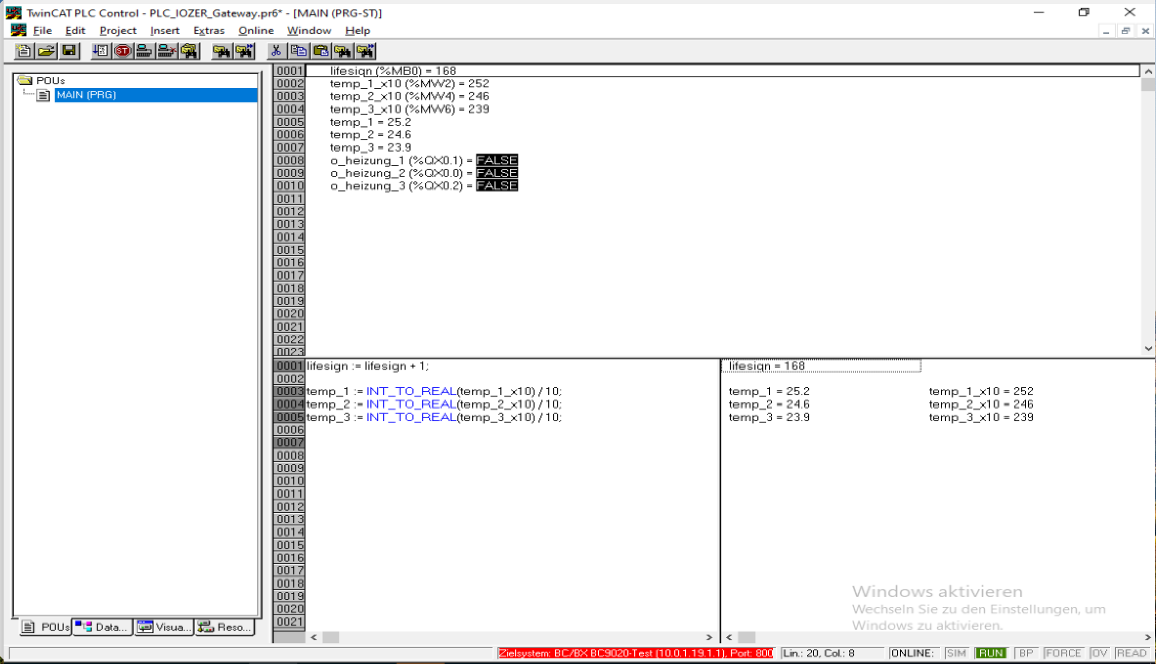
The screenshots were taken at different times and can therefore show different measurements. Compare the current displays during your test:
- Change the temperature of one sensor, for example by warming it with your hand.
- Wait for the next 1-Wire poll and forwarding operation.
- Check the corresponding IOZER datapoint, the correct PLC memory word, and the
REALtemperature. - Repeat the test for the other two sensors.
A changing life sign alone does not confirm successful writes to the temperature registers. The PLC online view provides direct feedback. This register layout contains no separate validity or timestamp value for the temperatures; if updates stop, a previously written value can remain in memory.
Troubleshooting
| Symptom | Possible cause and check |
|---|---|
| A sensor is missing or provides no value | Check 1-Wire wiring, sensor address, activation, and temperature value T. |
| BC9020 is not connected | Check its IP address, port 502, the network, and IOZER mode Master (Client). |
| IOZER shows temperatures but the PLC does not | Check data targets, Forward to data target, disabled Read only, and register addresses. |
| Temperature is wrong by a factor of ten | Check Scale = 0.1 at the Modbus target and division by 10.0 in the PLC program. |
| A negative temperature appears as a large positive number | Use Modbus type Int16 and PLC type INT. |
| Sensor values are swapped or overlap | Check mapping 16385 → %MW2, 16386 → %MW4, 16387 → %MW6 and reserved memory areas. |
| Life sign changes but temperatures remain unchanged | The life sign is a read operation. Check temperature write targets and forwarding separately; an unchanged sensor value does not cause another write. |
| Communication fails after a short time | Check the watchdog mode and timing margin against actual read or write intervals. |
| Modbus reports a server error | Also check the BC9020 K-bus configuration and diagnostics. |
Result and extension
IOZER integrates three 1-Wire temperatures into the PLC project. Each value occupies one holding register and is available in the BC9020 as an INT in tenths of a degree and as a calculated REAL value. Add further sensors using additional datapoints and free, non-overlapping register and flag addresses.