Quick start
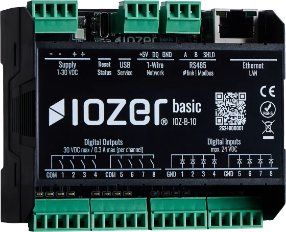
This page guides you through the initial commissioning of IOZER basic (IOZ-B-10) in a control cabinet or suitable distribution board. It is intended for electricians and integrators who need to connect the device, bring it onto the network, and prepare it for automation.
Installation, wiring, and commissioning may only be carried out by qualified personnel. Work only while the system is de-energized, use a suitable SELV/PELV power supply, and observe the safety information and all permitted electrical limits.
Direct connection to mains voltage, such as 230 V AC, is not permitted. This also applies to the relay outputs.
Preparation
Check the following before installation:
- Device type: IOZER basic (IOZ-B-10)
- Power supply: 7–30 V DC, SELV/PELV, typical power consumption < 5 W
- Conductor cross-section for the pluggable screw terminals: 0.14–0.75 mm² / AWG 26–18
- Installation location: enclosed operating location, IP20, 0 °C to +50 °C, non-condensing environment
- Access to Ethernet or Wi-Fi for initial configuration
1. Installation
Mount IOZER basic on a 35 mm DIN rail according to EN 60715.
Record the serial number or keep the QR code on the device or packaging available. It is used during the initial Wi-Fi setup.
2. Electrical connection
Carry out electrical wiring only while the system is de-energized. Before applying power, check polarity, short circuits, and that all terminals are secure.
| Connection group | Terminals | Notes |
|---|---|---|
| Power supply | V+, GND |
7–30 V DC; duplicate terminals for loop-through wiring |
| Digital inputs | GND, 1–4; GND, 5–8 |
8 galvanically isolated inputs, arranged in groups of four, max. 24 V DC |
| Digital outputs | COM, 1–4; COM, 5–8 |
8 normally open (NO) relay outputs, arranged in groups of four |
| 1-Wire | +5V, DQ, GND |
1-Wire bus with 5 V supply |
| RS485 | A, B, SHLD |
Modbus RTU; prepared for IOZER link; enable bus termination with the jumper if required |
| Ethernet | RJ45 | 10/100 Mbit |
| USB-C | USB | Service interface |
Observe the following for inputs and outputs:
- Digital input signals:
0at <= 2 V DC,1at >= 5 V DC; the range in between is undefined. - Relay outputs: max. 30 V DC, max. 300 mA per channel, max. 10 VA.
- Each digital input and digital output has its own status LED.
Additional limits are listed in the technical data.
3. Check setup mode
Switch on the power supply. During initial commissioning, the device starts in setup mode. This is indicated by the RGB status LED flashing blue. Additional indications are described under Status LED and reset button.
If the device is not in setup mode, press the reset button twice. The device will then make the initial configuration available again.
4. Open the web interface
Connect to the device using Wi-Fi or Ethernet.
| Connection | Procedure | Address |
|---|---|---|
| Wi-Fi | Scan the QR code or connect manually to the SSID IOZER-<SERIAL_NUMBER> |
http://192.168.198.1 |
| Ethernet | Connect a computer to the appropriate network or configure it with a static address | http://192.168.199.1 |
The setup access point uses WPA2 encryption. The SSID and password are printed on the product packaging label. The password is also included in the QR code on the packaging and on the device.
When connected over Wi-Fi, the setup page should open automatically in the browser. If it does not, open the appropriate address manually.
The default credentials are:
| Field | Value |
|---|---|
| Username | admin |
| Password | iozer |
The factory-set password must be changed on the first login in normal operating mode. The firmware requires this change before regular configuration and operation are available. Choose your own suitably complex password.
5. Configure the basic settings
After logging in, configure the settings required for the project:
- Network: DHCP or static IP, Wi-Fi client or access point, gateway, and DNS
- Time base: time zone and NTP if timestamps, logs, or schedules are used
- Interfaces: RS485 role, Modbus RTU/TCP, 1-Wire, MQTT, and REST API according to the project requirements
- Datapoints: unique names, data types, units, and bindings for inputs, outputs, Modbus, 1-Wire, or MQTT
- Users and API access: enable HTTPS; assign roles, passwords, and API tokens only as required
Events can then be created with Blockly or JavaScript for local automation. See also Datapoints and Programming.
6. Perform a functional test
Save and apply the configuration. Then start I/O & Interfaces using Activate I/O. Digital I/O, 1-Wire, Modbus, and MQTT do not start automatically in setup mode. Starting the program and starting I/O are separate actions; a running program alone does not activate the interfaces.
For subsequent normal operation, check both autostart settings under Settings → General and the initial and stop states of each output.
Before handover, check at least the following:
- The power supply and status LED behave as expected.
- Digital inputs switch cleanly and are displayed correctly in the web interface.
- Relay outputs switch only permitted loads within the specified limits.
- The RS485 bus has the correct polarity and is shielded and/or terminated if required.
- 1-Wire devices are detected and return plausible values.
- MQTT, Modbus TCP, or REST connections reach the intended target system.
- Local logic starts, stops, and responds as intended.
Document the IP address, access concept, connected terminals, datapoint names, and integration parameters for operation and maintenance.
7. Firmware and handover
Before placing the device into productive operation, check whether an approved firmware update is available. Updates can be installed over the air or by uploading a file through the web interface.
Further information: Release notes.