Electrical connection
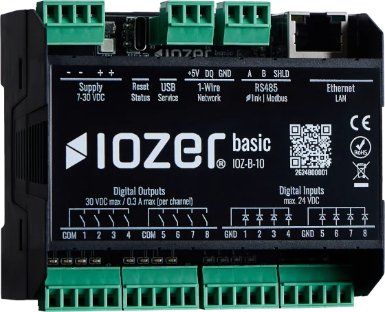
This page describes the connections of IOZER basic (IOZ-B-10) and the most important wiring requirements for installation in a control cabinet or suitable distribution board.
Electrical connection may only be carried out by qualified personnel and only while the system is de-energized. Use a suitable SELV/PELV power supply and check the wiring before switching on the power.
Direct connection to mains voltage, such as 230 V AC, is not permitted. This also applies to the relay outputs.
Power supply
IOZER basic is supplied with DC voltage through V+ and GND.
| Connection | Value |
|---|---|
| Supply voltage | 7–30 V DC |
| Power consumption | typ. < 5 W |
| Terminals | Duplicate terminals for loop-through wiring |
Observe the polarity of the supply terminals. Before switching on the power, check the polarity, ensure there are no short circuits, and verify that the terminals are secure.
Digital inputs
The digital inputs are galvanically isolated and arranged in two groups of four inputs.
| Connection group | Terminals | Notes |
|---|---|---|
| Inputs 1–4 | GND, 1, 2, 3, 4 |
Shared ground terminal for each group |
| Inputs 5–8 | GND, 5, 6, 7, 8 |
Shared ground terminal for each group |
Signal levels:
| Signal | Level |
|---|---|
0 |
<= 2 V DC |
1 |
>= 5 V DC |
| Undefined | > 2 V DC to < 5 V DC |
The input voltage must not exceed 24 V DC. Each input has its own status LED.
Digital outputs
The digital outputs are normally open (NO) relay contacts arranged in two groups of four outputs.
| Connection group | Terminals | Notes |
|---|---|---|
| Outputs 1–4 | COM, 1, 2, 3, 4 |
Shared COM terminal for each group |
| Outputs 5–8 | COM, 5, 6, 7, 8 |
Shared COM terminal for each group |
Limits:
| Parameter | Value |
|---|---|
| Output voltage | max. 30 V DC |
| Output current | max. 300 mA per channel |
| Switching capacity | max. 10 VA |
Each output has its own status LED.
Communication interfaces
The following sections describe the wired communication interfaces of IOZER basic.
RS485
The RS485 interface supports Modbus RTU. It is prepared for IOZER link to connect IOZER expansion modules.
| Terminal | Function | Note |
|---|---|---|
A |
RS485 data line A | Connect continuously to A on the remote devices |
B |
RS485 data line B | Connect continuously to B on the remote devices |
SHLD |
Shield connection | Connect the shield according to the system design |
Operating modes
| Operating mode | Use |
|---|---|
| Modbus RTU master | IOZER basic polls external Modbus RTU devices |
| Modbus RTU slave | IOZER basic provides data to an external Modbus master |
| IOZER link | Prepared for connecting IOZER expansion modules |
The operating mode is selected in the device configuration. Only devices with compatible operating modes, baud rates, parity, stop bits, and addressing should be operated on the same RS485 bus.
Wiring
Wire RS485 as a line bus using a twisted pair for A and B. Avoid star configurations, rings, and long stubs. Polarity must remain consistent throughout the entire bus.
Use a shielded bus cable for longer distances or in environments with electrical interference. Do not connect the shield at multiple arbitrary points with different potentials. In typical control cabinet installations, connect it at one end or according to the grounding and shielding design of the system.
Termination
The 120-ohm bus termination can be enabled using a jumper. Enable termination only when IOZER basic is located at one end of the RS485 bus.
| Position on the bus | Termination |
|---|---|
| End of the bus | Enable 120 ohms |
| Middle of the bus | Do not enable termination |
| Short laboratory or test wiring | Only if required |
An RS485 bus is normally terminated at both physical ends. Intermediate devices are not terminated.
Commissioning
- Wire
AandBconsistently on all devices. - Assign a unique bus address to every Modbus RTU device.
- Configure matching baud rate, parity, and stop bits on all devices.
- Enable termination only at the two ends of the bus.
- Check shielding and reference potential according to the system design.
- If communication fails, first check polarity, termination, bus parameters, and duplicate Modbus addresses.
1-Wire
The 1-Wire connection is used to integrate simple sensors, such as temperature sensors. IOZER basic provides +5V, DQ, and GND.
| Terminal | Function | Note |
|---|---|---|
+5V |
Sensor supply | For 1-Wire devices with a 5 V supply |
DQ |
Data line | Also referred to as DATA or 1W |
GND |
Reference potential | Route together with DQ |
| Property | Value |
|---|---|
| Maximum number of sensors | 32 |
| Supported sensor types | DS18B20, DS2438 |
Wiring
For new installations, three-wire wiring using +5V, DQ, and GND is recommended. This makes the installation more robust and easier to expand than a purely parasitic supply through the data line.
Shielded telecommunications or installation cables, such as J-Y(St)Y 2x2x0.8 or comparable KNX/twisted-pair cables, are suitable for typical installations. For maximum interference immunity, DQ and GND should use the same twisted pair. With cables similar to J-Y(St)Y, the shield or drain wire is normally not connected for 1-Wire and is not looped through at terminals.
Category cables may be electrically suitable but often have smaller conductor cross-sections. For longer cable runs or sensors with higher current consumption, larger conductor cross-sections and a topology without star branches are preferable.
Topology
1-Wire is more sensitive to unsuitable topologies than conventional fieldbuses. Keep the bus layout as simple as possible.
| Topology | Rating | Note |
|---|---|---|
| Line | Recommended | Connect sensors one after another along one cable |
| Bus with short branches | Suitable | Keep branches as short as possible |
| Tree | Limited suitability | Only with manageable cable lengths and device counts |
| Star | Limited suitability | Only for small installations |
| Ring | Not permitted | Do not electrically connect the beginning and end |
For mixed topologies, the restrictions of the least favorable section apply. If several sensor lines are required, it is usually better to plan them as cleanly separated lines instead of building one large meshed structure.
Parasitic power
Some 1-Wire sensors can be powered parasitically through DQ and GND. Use this mode only if the sensor, bus master, and firmware explicitly support it. For new installations, a supply using +5V, DQ, and GND is generally easier to maintain.
For simple DS18B20 sensor elements, parasitic operation may require connecting VDD to GND at the sensor. This bridge may only be installed at the sensor and according to its data sheet. The +5V output of IOZER basic must not be short-circuited.
Commissioning
- Connect sensors one at a time where possible and detect each one using a 1-Wire scan.
- Document sensor serial numbers together with their installation locations.
- Create datapoints with unique names and units.
- If readings are unstable, first check the topology, branch lengths,
DQ/GNDpair assignment, and power supply. - Avoid cables with strong interference, long parallel routing alongside load cables, or unclear terminal points.
Checks before switching on
- Supply voltage and polarity checked
- No connection to mains voltage
- Terminals tightened securely
- Suitable conductor cross-section and ferrules used
- Input and output groups assigned correctly
- RS485 shielding and termination checked against the bus layout
- 1-Wire topology checked; no ring,
DQandGNDrouted as a twisted pair
Additional limits are listed in the technical data.